|
|
MECH 200
Engineering Drawing
Lab 3:
Assembly Drawings
|

Objective
- To measure the critical
dimensions of each part of a rotor assembly using a micrometer or vernier caliper.
- To make CAD drawings for all
the parts.
- To generate a single front view
assembly drawing of the rotor assembly.
- To understand the concept of
prototype drawings and use AutoCAD commands like pline,
block, wblock, explode, leader, etc.
Introduction & Concepts
Lab 3 is an exercise in the preparation of an assembly
drawing. This lab also expands your knowledge of AutoCAD by covering the
concepts of blocks and polylines. These AutoCAD
features are used to create your assembly drawing from the individual part
drawings and notate it with leader arrows.
This lab is also the best opportunity to introduce the AutoCAD concept
of prototype drawings. A prototype drawing lets you avoid all the
hassle setting up layers, limits, dimension styles, linetypes,
titleblocks and drawing
scales every time you begin a new drawing.
Assembly Drawing
Assembly
drawings are illustrations used to explain how parts fit together in a larger
assembly.
The assembly
drawing illustrates more than just the location of each part. Each component is
identified by a leader, at the end of which is a numbered balloon.
Each numbered balloon has a corresponding entry in the parts table. Each row in
the parts table corresponds to a different numbered part, and contains the full
part description.
There are two kinds of assembly drawings:
- Pictorial assembly drawings
- Orthographic
assembly drawings
In Lab 2, you created a three-view orthographic
projection of a bracket. That kind of drawing provides detailed information
required to produce a part, and is called a working drawing by
the design industry. In this lab, there would be 5
working drawings accompanied by an assembly drawing. The working drawings
should contain at least 2 orthographic views of each part of the rotor
assembly.
Figure 1 shown below is a pictorial
assembly drawing. These types of drawings are very useful to indicate the
method of assembly, and are often used in technical manuals. Figure 2 of
the rotor assembly is an orthographic assembly drawing.
Figure 1: Pictorial Assembly Drawing of a truck
transmission's Transfer Case
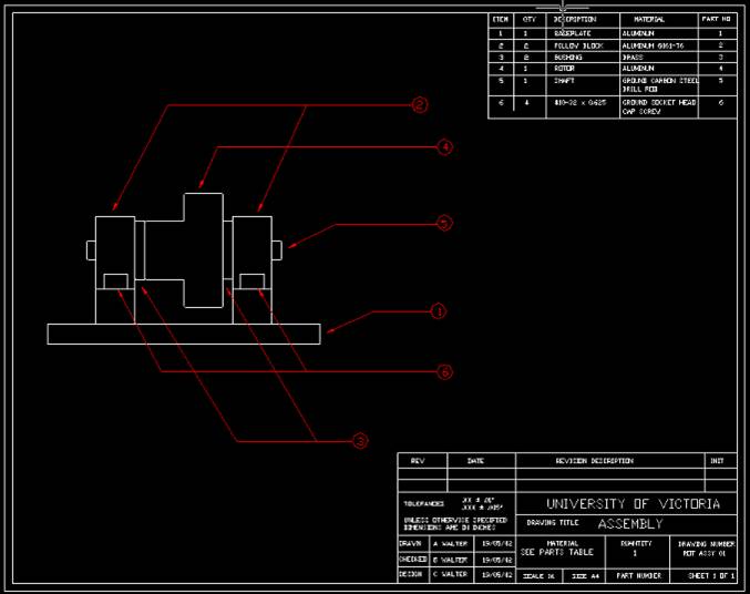
Figure 2: An Orthographic Assembly Drawing of the rotor assembly
Prototype Drawings
AutoCAD supports a feature known as Prototype
Drawings, in which you can designate any drawing file to serve as the starting
point for new drawings. This saves a lot of time as most of the initializations
like setting up the units, layers, dimensioning styles,
line types, etc are preset. Title blocks and revision blocks can also be used
with small changes. Most companies that use AutoCAD have a standard library of
prototype drawings, with each member of the library corresponding to a
different size of paper.
Blocks
If your drawing contains many copies of the same
object (such as a chair in an office layout drawing), that object is a good choice for a
block. Blocks are one of AutoCAD's
strategies to keep drawing file size down. The larger and more complex a
drawing file becomes, the greater the demand on memory and disk space. If a
chair symbol requires 12 objects (line, arc, etc.) to draw and if there are 100
copies of it in a drawing file, there are a total of 1200 objects to store. By
storing a master definition of the chair in a special place within the drawing
database called the block table, AutoCAD
can reference the chair's common features without the overhead of 99 other copies.
Whenever you redefine the chair block, each of its copies, (called instances
by AutoCAD) are automatically updated to reflect the changes.
How Blocks & Layers Relate To
Each Other
Any given block can contain objects drawn on different
layers, and can therefore be quite a hassle to manage with AutoCAD's layer
controls. Imagine a chair block defined with the seat, armrests, and back all
on custom layers of the same name. This block would ignore the layer control
settings of whatever layer it was drawn on in favor of the settings on those
custom layers. Worse yet, this block would create those layers in
any new drawing it was inserted in, much to the chagrin of the hapless person
who thought they were inserting a nice inoffensive chair symbol into their
drawing! In order for a block to be as well behaved as other AutoCAD objects
such as lines, arcs and circles, it must be made from objects drawn on
layer 0: Objects living on all other layers will make your block disobedient
to the layer controls, and will result in the creation of these layers in any
new drawing you insert them in.
Before you create a block from any objects, use the chprop command to move the parts you want to layer
0. This will guarantee that your newly created block contains no undesired
blocks or layers, and will therefore behave itself in your drawing's layer
table.
The Block Command
Creating a block within AutoCAD is easy. Invoke the
block command by typing block at the command line, and provide AutoCAD with a name,
an insert point, and then the objects you want to make up the block. The insert
point should be chosen correctly bearing in mind that AutoCAD will insert,
scale and rotate the block around this point. When you complete the block command,
all the objects you have selected will be deleted as they would be transferred
to the block table.
The WBlock
Command
With the block command described above only creates a
local version of the block. It is only available within the drawing it was defined
in. To transfer any blocks between drawings, you'll need to use the wblock
command. This command opens up a create
new file dialog box (The same one you see when starting a new drawing)
from which you are prompted to name the block as an AutoCAD drawing file. Next,
you are prompted for the block name and/or an insert point followed by the
objects you want to make up the block.
The Insert Command
The insert
command is used to place instances of the blocks you have defined. The first
thing you will be asked when you run this command is the name of the block.
Once you have named the block you must choose the insert point, followed by the
x and y scale of the block instance. Hitting the <Enter> key twice will
select scales of 1 for both x and y. Finally, you must enter the rotation of
the block (relative to its orientation when you defined it)...Just remember
that angles are measured counterclockwise in AutoCAD.
The Explode Command
Eventually, you'll want to revise or otherwise change
a block you have defined. To begin this task you'll need to "break
open" one of your block instances in order to be able to get at the lines,
arcs, and other objects inside: This is achieved with the explode
command.
Once you have exploded a block, you are free to edit
the stuff that was once inside it. When your edits are complete, you redefine
the block by simply running the block command and
giving your new block the same name as the old one you exploded. AutoCAD will
update the block definition, replacing all of its instances in your current
drawing.
Dim Leader
AutoCAD has an automated dimension command called leader.
As a dim mode command, you'll need to type dim at the command line in order for
it to work. Once you have started the leader command, AutoCAD will prompt you
for the location of the arrowhead, followed by the next point of the leader.
When you are tired of mouse-picking the points that define the line segments of
the leader, simply hit the < Enter > key to go to the next phase of the
command: Entering the leader text. In this lab, the only leader text you
require is a number from 1 to 5, so type in the number you want and hit the
< Enter > key to end the command. Draw a balloon around the number using
the circle command and trim the end of the leader with the trim
command
Polylines
Until now you have used the line
command whenever you needed to draw a line. The pline
command operates exactly the same as the line command, except it creates polylines. These super-powered
lines can contain as many line segments as you want, and are considered one
object by AutoCAD. Consider a rectangle
made of polylines. To move the
rectangle, you need not select each line of the as you would have done if line
command were used.
Another big benefit of polylines
is how they work in conjunction with the offset command. In the past, you had
to offset the outer boundary of the plate in Lab 1. If that boundary had been a
single polyline instead of a collection of lines, the
offset generated inner boundary would not have required any trimming after the
fact.
Making a Polyline
Frame
As a demonstration of the power of polylines,
let's create a letter size (printer paper) drawing frame. This frame will be
used later for creating the prototype drawing. The size of the paper is 11” x
8.5” and the printable area is 10.75 x 8.25 inches.
- Begin by opening a new drawing
file from AutoCAD.
- Run the limits command
and set the lower limits to (0, 0) and the upper limits to (11, 8.5).
- Run the pline
command, entering the following coordinate data
0.125, 0.125
@10.50< 0
@8.00<90
@10.50<180
@8.00< 270
enter
- Run the offset command with a
value of 0.1. Pick the frame and offset it to the inside.
- Save this drawing as frame.dwg
This will
create the boundary for your drawing and can be used to create the prototype
drawing.
The Pedit
Command
If you've done any drawing of polylines
by now, you've probably wondered how to change the coordinates of individual
points after the polyline's creation: This (and many
other polyline editing operations) is accomplished
with the pedit
command, which allows you to do any of the following operations:
- Close an open polyline / Open a closed polyline.
- Join line segments to the
current polyline.
- Edit (change the locations of)
the vertices of the current polyline.
- Spline the current polyline; and. Decurve (un-spline) the current polyline.
Procedures
Creating the Prototype & Part
Drawings
- Open the frame.dwg drawing and
use it to make the prototype drawing.
- Make the title block and the
revision table as discussed in Lab 2.
- Define custom layers for
dimensioning, hidden lines, center lines, load the different types of
lines, and define ltscale and dimscale properly.
- Once you have done this, save
the drawing as proto.dwg. This drawing will be the prototype drawing that
can be used to make all the other drawings.
- When you open this prototype
drawing to make any part drawing, remember to save it by a different name
and change the contents in the title block.
- Make part drawings for each
component in such a way that the part is completely defined, i.e. try to
make the drawings in at least 2 views.
Creating the Assembly Drawing
- Open the prototype drawing i.e.
proto.dwg.
- Use the ddlmodes
command to set up layers named 1-baseplate, 2- pillow-block, 3-bushing, 4-rotor, 5-shaft. You will insert each part into its
corresponding layer. Set the current layer to 1-baseplate.
- Use the insert command to insert the pillow
-block into the current layer.
- Set the current layer to 2-pillowblock and get the pillow block
inserted in your drawing. Since there are two pillow blocks, you will have
to insert the pillow block again and rotate it through 180 deg to fit the
other side. Insert each of the parts into their corresponding layers in a
similar manner.
- Your rotor assembly drawing
should be assembled to look like the one in Figure 2. You will have
to explode some of the parts and trim them a bit to get the
assembly drawing looking right. Be careful whenever you explode a
block, for the drawing entities inside it will return to layer 0. You must
ensure that these lines, arcs and circles are put back on the layer they
belong to with the chprop command,
so be ready to turn off all of the layers except the ones you need.
Verify that
everything in your drawing is where it should be by selectively turning off
each layer from 1 to 5. If each corresponding part does not turn off with its
parent layer, there is an error. Each block must be inserted on the appropriate
layer, and exploded and trimmed block contents must be
chprop'ed back to this layer.
Deliverables
- Provide individual drawings in
at least 2 Orthographic views for the Base-plate, Shaft, Wheel, Bushings
& Pillow Blocks.
·
All the drawings should be made to 1:1 scale & on
a letter size paper of dimensions 11” x 8.5”.
·
Use inches as the units for all the drawings.
·
Each drawing should include the title block, which
must be locked into the lower right hand corner of the drawing frame and the
revision table. The assembly drawing should have the parts table.
- The final assembly drawing (Figure
2) should be made using all the part drawings.